Sample scientific and engineering R&D efforts are shown here. More on Gas Turbine, Supercritical Fluid Technology, Liquid Rocket Engine (LRE), Combustion Instability, Light-Activated Volumetrically-Distributed Ignition with Nanostructured Materials, Nanotechnology and Fuels, etc will be coming up soon.
RESEARCH IMPACT:
Dr Chehroudi's past research projects had contributions and impacts in a number of areas. First, on account of the multidisciplinary nature of most efforts, they enhanced inter- and intra-organizational communication and created synergistic joint efforts. Second, many of them led to fundamental understanding of the underlying physics of the problem. Third, they substantially enriched the visibility and scientific credibility of the division. Fourth, they led into tremendous performance improvement on the existing products and led to either new products/technologies or product ideas. Fifth, many of them won technical merit awards from prestigious scientific/engineering societies (listed in the AWARDS section). Sixth, sustained award-winning high-quality publications and reports with useful results which encouraged continued support by funding agencies.
-
Nanotechnology and Applied Combustion: Use of Nanostructured Materials for Light-Activated Distributed Ignition of Fuels with Propulsion Applications:


The discovery that a nanostructured material behaves differently than the bulk material opened the door to many exciting opportunities. One such opportunity is the observed ignition of single-walled carbon nanotubes (SWCNTs)  with a camera flash. In this paper, results from distributed ignition of fuels with SWCNTs are presented which motivated further investigation of dry SWCNT samples. Consequently, a major part of the paper focuses on ignition characteristics of SWCNTs with an ordinary camera flash. A preliminary result from graphene sheets is also presented. The primary objective of this work is to use nanostructured materials as means for distributed ignition and combustion improvement in propulsion applications. Examples are homogeneous-charged compression ignition (HCCI) engines, liquid rocket fuel sprays, and enhanced flame stabilization in gas turbine engines.
The idea was originally proposed by Dr Chehroudi in April 2003 and the first patent filed in July 2004 after initial investigations. Based on tests conducted so far, this new ignition method is considered as a potential enabling technology for volumetric and distributed ignition of liquid fuel sprays and gaseous fuel-air mixtures with the lowest incident power intensity possible. This means remote and spatial ignition within any desired region defined by the shape of the light from a pulsed light source.
In this paper, effects of incident pulsed-light exposure duration and wavelength between 350-1500 nm on minimum ignition energy (MIE), effects of sample physical compression (i.e., packing) on ignition chara cteristics, and the impact of iron (Fe) nanoparticle content in dry (no fuel) SWCNTs samples are presented. Initial measurements of the sound pressure level (SPL) from the photoacoustic phenomenon as well as ignition of graphene oxide are also presented. It appears that the wavelength of the illumination source does not play an important role as compared to the flash duration, at least within the range studied here. Data suggests that a lower energy-per-pulse is needed to initiate ignition when a shorter flash pulse duration is used. For example, only 30-35 mJ/pulse is required at pulse width of ~0.2ms to initiate ignition of the as-produced fluffy samples in standard air, whereas at 7ms duration, it needs 80-90 mJ/pulse .
For lightly-compressed samples, MIE trend remains unchanged and similar to that of the as-produced batches; otherwise, it increases with the level of the compression. Samples with Fe (metallic nanoparticle) content as low as 18% by weight can be ignited in air with a camera flash. Averaged intensities between 10 to 150 W/cm2 are required for distributed ignition of SWCNTs. This is a factor of 80 less than cases where lasers (pulsed or cw) are used in coal particles. However, graphene oxide required much higher input energy, a disadvantage to keep in mind in applications.
- Injection of Liquid Rocket Propellants into High-Pressure Supercritical Environment:


Advanced Technology Consultants has been conducting R&D in propellant injection issues pertaining to liquid rocket engines for over 15 years. One of the areas of expertise in which ATC has achieved world-class performance and prominence is the understanding of the injection under supercritical condition similar to what occurs in (liquid) hydrogen/oxygen cryogenic liquid rocket engines such as space shuttle main engine (SSME).
Our work on supercritical injection, conducted at Air Force Research Laboratory (AFRL) and in the context of liquid rocket engines, is globally recognized as original and pioneering. He started his R&D work on high Reynolds number injection of jets in 1998, at a time when no model for such cases existed, and in general not much quantitative information was available, for use in a systematic computational simulation. His leadership in this area culminated to a ground-breaking finding, which quantitatively proved that supercritical jets, for the most part, appeared like 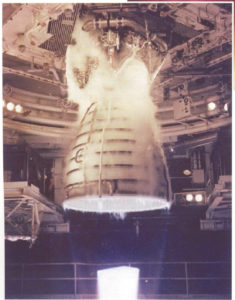 incompressible variable-density jets. Application of Fractal Analysis to the supercritical jets was considered for the first time. The fractal dimension measurements for the boundary of such jets supported the notion that such jets appear as incompressible variable-density jets. He also conducted modeling efforts on supercritical jets resulting to the only validated model in the literature. For example, for the first time, a successful model for the growth of the mixing layer in coaxial injectors under supercritical condition was proposed by Chehroudi which is currently the only reliable one being used by design engineers and modelers.
NOTE: Contact Advanced Technology Consultants for consulting needs and opportunities in this area.
The following technical review article appeared as an invited paper in an special volume of the Combustion Science and Technology Journal dedicated to supercritical fluids and their applications. For a list of this and other papers click here: CST Journal.
Injection of Fluids into Supercritical Environments
Chehroudi et al.
An Invited Contribution to An Special Volume of the Combustion Science and Technology Dedicated to Supercritical Fluids
(Volume 178, Numbers 1-3, Number 1-3/January 2006, pp. 49-100(52))
This work summarizes and compares the results of systematic research programs at two independent laboratories regarding the injection of cryogenic liquids at subcritical and supercritical pressures, with application to liquid rocket engines. Both single jets and coaxial jets have been studied. Cold flow studies provided valuable information without introducing the complexities of combustion. Initial studies utilized a single jet of cryogenic nitrogen injected into a quiescent room temperature nitrogen environment with pressures below and above the thermodynamic critical pressure of the nitrogen. Later, the work was extended to investigate the effects of a co-flowing gas. Parallel to this work, combustion studies with cryogenic propellants were introduced to understand high pressure coaxial injection phenomena with the influence of chemical  reaction. Shadowgraphy and spontaneous Raman scattering were used to measure quantities such as growth rates, core lengths, turbulent length scales, fractal dimensions, and jet breakup regimes. It is found that
Table of Contents
-
- Introduction
- High pressure combustion in liquid rocket engines
- Thermo-physical properties and issues specific to supercritical conditions
- Test Benches and Experimental Set-ups
- AFRL test bench
- DLR cryo-injector test facility
- DLR high pressure combustion test facility P8
- Diagnostic methods
- Shadowgraphy
- Raman scattering
- Single Jet Investigations
- Jet surface
-
- Phenomenology at trans- and supercritical pressure
- Length scale analysis
- Fractal analysis
- Jet decay
- Visualization of jet core length
- Center line density decay
- Jet spreading angles
- Jet disintegration under the influence of an external acoustic field
- Modeling and simulation single jet injection at high pressure
- Phenomenological model of the jet growth rate
- Numerical simulation of injection at supercritical pressure
- Coaxial Jet Investigations
- Non-reactive coaxial jet atomization
- Visualization of coaxial LN2/He-injection
- Density measurements in a coaxial LN2/GH2-jet
- Coaxial LN2/GN2-injection under the influence of an external acoustic field
- Hot fire tests: LOX/GH2-injection
- Non-reactive coaxial jet atomization
- Summary and Conclusions
- Acknowledgements
- Introduction
In 2009, Dr. Chehroudi was an Invited Speaker to Swiss Federal Institute of Technology Zurich (ETH) for a presentation on Supercritical Fluids and Injection Processes of Relevance to High-Pressure Combustion, Colloquium in Thermo-Fluid Dynamics (Kolloquiums Thermo- und Fluiddynamik).
- A Physical Hypothesis for the Combustion Instability in Cryogenic Liquid Rocket Engines:

Acoustic combustion instability has been one of the most complex phenomena in liquid rocket engines, and therefore difficult to fully understand, control, and predict particularly in the design of high-power rockets. The difficulty arises from the emergence of oscillatory combustion with rapidly increasing and large pressure amplitudes. This leads to local burnout of the combustion chamber walls and injector plates which is caused through extreme heat-transfer rates by high-frequency pressure and gas velocity fluctuations, see Harrje and Reardon and Yang and Anderson. It is thought that resonance acoustic modes of the thrust chamber, amongst them the transverse modes being the most troublesome, are excited through the energy provided by the combustion. The amplification process is thought to include a feedback of information from the acoustic field to the injector or near-injector phenomena which in turn tends to reinforce the combustion-to-acoustic-field energy transfer processes. The energy transfer reasoning alone is the widely cited general principle by Lord Rayleigh. In essence, he made a phasing argument and stated that the interaction between the combustion heat release and the acoustic field is the strongest if heat is added in a region of space and at the time when the acoustic amplitude is the highest. Although this view has been useful to understand a part of the big picture, evidences gathered by past investigations attributed combustion instability to a complex interaction of the external acoustic field with the fuel injection or near-injector processes as a feedback mechanism, thereby leading to incidences of instability in rocket engines. See, for example, Heidemann and Groeneweg [4], Anderson et al., and Hulka and Hutt. For this and other reasons, controlled studies have been conducted probing into the effects of acoustic waves on gaseous and liquid jets from a variety of injector hole designs. A series of investigations concentrated on disturbances induced from within the injection system. They considered the effects of acoustic fields on many phenomena such as flow structure, vortex pairing, and shear layer growth rate in the initial region of the jet (for example, see a short review article by Kiwata, et al.). More relevant to the work reported here, are a few reports and articles on gaseous and (in particular) liquid jets under the influence of external (transverse and longitudinal) acoustic fields. These have been reviewed in Chehroudi and Talley and Davis and Chehroudi.
In this work, however, the author proposed a physical picture based on experimental results and intuitive arguments to describe a possible coupling nature/strength between the chamber acoustics and injectors or near-injector processes in cryogenic liquid rocket engines.
SUMMARY and CONCLUSION
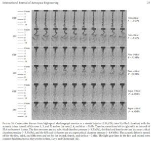
In summary, an attempt has been made to portray a fluid dynamical perspective and link a hypothesis proposed here to observations made in cold flow injector studies, subscale fired engines, and full-scale production engines with an aim to offer a sketch of a theory being consistent with most observations pertaining to combustion instability.
Based on the author’s previous work on intrinsic sensitivity of the dark-core length in a coaxial-jet-like injector in cold sub- and supercritical conditions, it is proposed that a similar phenomenon pertaining to the dark core in impinging-jet injectors is to be considered, attempting to offer underlying fluid mechanical reasons for the injector-caused combustion instabilities in LRE. The basic premise here is that when an important dynamic feature, such as the dark-core or breakup zone, of an injector design becomes sufficiently sensitive to thermofluid parameters of its environment, it is highly likely that this could strengthen the feedback link thought to be critical in the amplification process and hence push the system into an unstable operating state. Evidences cited suggest that the enhanced sensitivity of impinging-jet injectors to their environment occurs when the mean dark-core or break up length of one or both jets forming the impingement reaches a critical value, being of the same order as the pre-impingement length. Feasibility of such a scenario is explored by comparing the range of pre-impingement length values for engines and some recently measured dark-core lengths for cryogenic jets at density ratios of interest. It is then hypothesized that the stable-unstable transition boundary in the Hewitt stability plot is when the core length of one or more of the jets of the impinging jet injector becomes comparable to the pre-impingement distance. This proposed hypothesis is able to offer a consistent explanation of why an engine design based on impinging jets becomes unstable when Hewitt stability parameter (dn/V) is decreased. While work is needed to make a transition from a hypothesis to an established fact, there is sufficient published information in favor of the hypothesis to make it a strong possibility amongst others previously proposed. Finally, the readers are cautioned that as some atomization results from cold studies are linked to fired sub- and full-scale engines, more targeted investigations guided by the hypothesis on the dynamic behavior of the dark-core length and width in cold and fired coaxial and impinging-jet injectors are justified and highly recommended.
Click on the right slide to see Dr. Chehroudi's presentation of the Unified Injector Sensitivity Theory at the 47th American Institute of Aeronautics and Astronautics (AIAA) Aerospace Sciences Meeting, Orlando, Florida, January 5-8, 2009.
Click on the image to see a video of combustion instability in liquid rocket engine.
- Raman Scattering Measurements in the Initial Region of Sub- and Supercritical Cryogenic Jets of Relevance to Propulsion:
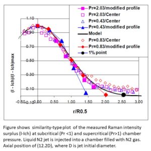
A high-pressure chamber is used to investigate the be-havior of liquid N2 jets having an initial temperature less than the critical temperature of N2, into ambient N2 at greater than the critical temperature, at various pressures ranging from less than to greater than the critical pressure.
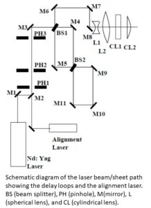
Two-dimensional Raman scattering is used as a diagnos-tic tool. The injector was a straight tube with a length-to-diameter ratio of 100. The optical setup used a pulsed frequency-doubled Nd:Yag laser at 532 nm as an incident beam. Two-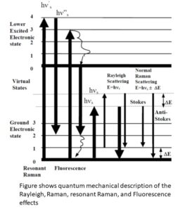 dimensional images were taken near the injec-tor and results were interpreted in terms of density plots. At subcritical ambient pressures, a strong Raman signal was obtained and only a small number of images were needed for averaging. Substantial reduction of this signal was observed at supercritical pressures due to jet radial growth and mixing. The radial profiles of the intensity-surplus exhibited self-similar behavior at all the condi-tions tested. These profiles were shown to have been broadened by the interaction of the laser sheet and the jet interface. At pressures near and above the critical pres-sure, the modified profiles tended to assume the self-similarity profile of gaseous turbulent jets. The initial growth rate of the jet as judged by the Raman signature also showed such a tendency towards gaseous turbulent jets. However, the differences in growth rates remained quite distinct, being nearly half the growth rate reported for gaseous jets. The initial growth rate was in reasonably good agreement with our earlier measurements using shadowgraphy if twice the FWHM of the normalized in-tensity plots was used.
Synopsis on Raman effect is presented here. When a transparent medium is irradiated, some fraction of the beam is scattered in all directions. If the medium contains particles of molecular dimension, a weak scattered radiation having the same wavelength is observed (Rayleigh scattering). When aggregates of par-ticles have sizes approximating that of the wavelength of the radiation, however, scattering becomes evident as the Tyndall effects or as a turbidity. Raman, in 1928, discov-ered that the wavelength of a very small fraction of the scattered radiation by certain molecules shifted in an amount dependent upon the chemical structure of the molecules responsible for the scattering. The theory of Raman scattering shows that the phenomenon results from the same type of quantized vibrational changes that are associated with infrared absorption. Therefore, the observed difference in wavelength corresponds to wave-length in mid-infrared regions. However, an important advantage of Raman over infrared spectra is that water does not cause interference. In addition, glass or quartz windows can be used instead of the inconvenient sodium chloride or other atmospherically unstable windows.
The Raman spectra are obtained by irradiating a sample with a powerful visible monchromatic source. The scattered signal is usually observed at 90 degrees to the incident beam with a suitable visible-region detector or spectrometer. The scattered radiation does not exceed 0.001 % of the source, as a result detection and measurement is difficult except for the resonant Raman which is explained below. The scattered light is of three types, Stokes, anti-Stokes, and Rayleigh. Rayleigh, which has exactly the same frequency as the excitation source, is substantially more intense than either two. Stokes peak lines are found at wavelengths larger (lower energies) than the Rayleigh peak while anti-Stokes are at smaller (higher energies) than the wavelength of the source. It is critical to realize that the magnitude of the Raman shifts are independent of the wavelength of excitation source. Although, superficially, the appearance of the Stokes shifts are similar to the Stokes shifts observed in fluorescence, they arise from fundamentally different processes. Generally, the Stokes lines are more intense than the anti-Stokes and for this reason usually only this part of the spectrum is observed. It is also important to indicate that fluorescence can interfere with detection of the Stokes shifts but not with anti-Stoke shifts.
The wave theory of Raman relates this effect to the change in polrizability of the molecule which may occur during its vibration. That is, the ease with which the electrons of the bonds can be distorted from their normal position by the excitation source. The wave theory cannot predict the fact that the Stokes lines are stronger than the anti-Stokes lines. Quantum mechanics, considers elastic (no net exchange of energy, like Rayliegh) and inelastic collisions ( like Raman effect) between photons an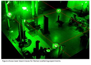 d molecules. In the latter, the vibrational energy of the bond is subtracted and added to the energy of the photon thus shifting its frequency, see Figure. It is important to indicate that the normal Raman (or spontaneous Raman) process is not quantized and depending on the frequency of the excitation, the molecule can assume any number of infinite virtual states as shown in Figure. The relative populations of the states in this figure are such that Stokes emission is much favored over the anti-Stokes. Also, the ratio of anti-Stokes to Stokes intensities increases with temperature as larger fraction of the molecules make transition and stay in the first vibrational excited state under such higher temperature conditions. The intensity of the normal Raman depends on the polarizability of the molecules, the source intensity, concentration of the scatterers, and other factors. In the absence of absorption, the intensity of Raman emission increases with fourth power of the source frequency (or ~ 1/λ4). However, care must be exercised at shorter source wavelengths (ultraviolet) as likelihood of the photodecomposition will increase particularly if sample is not flowing past the interrogation zone. Source frequencies must be chosen so it is not absorbed by the sample unless resonant Raman is considered. Normal Raman intensities usually are linearly dependent on the concentration of the molecule (similar to Fluorescence) unlike logarithmic behavior for the absorption. Raman signal is found to be polarized to a various degree depending on the type of vibration responsible for the scattering. Generally, the scattered Raman is more polarized when excited mode of vibration is symmetric when a plane-polarized radiation source is used (such as a laser). Depolarization ratio, defined as the ratio of the perpendicularly-polarized by the parallel polarized scattered Raman, is 0.022 for N2 molecule. Theoretically, it can be shown that depolarization ratio is ¾ for nonsymmetric vibration while always less than this value for the symmetric case.
When the excitation frequency falls within a frequency range of a molecule's (vibrational or electronic) absorption band in the visible or UV spectrum, the radiation is scattered by either resonance Raman or resonance fluorescence, see Figure. Both produce much more intense radiation than normal Raman. Resonance Raman intensities can be higher that normal Raman by up to 2 orders of magnitude. In resonance fluorescence, the absolute frequencies of the fluorescence do not shift when the source frequency is changed as long as it stays within the absorption band. However, the absolute frequency of the Raman (both normal and resonant) shifts with exactly the same amount as the changes in source frequency. Finally, in situations where the intensity of the source exceeds certain threshold power, coherent pumping of the molecules of the sample into an excited vibrational state occurs. This coherent frequency is equal to that of the laser minus the vibrational frequency. The power in the scattered radiation may itself cause further stimulated Raman emission by a repetition of the original process, producing a frequency equal to the laser minus twice the frequency of the vibrational mode that is involved in the scattering. Also, an unusual observation in stimulated Raman is the excitation of an intense anti-Stoke radiation which may even be stronger than the Stokes in some cases. It occurs as a result of the pumping of the molecules from ground vibrational state into upper excited states by the initial laser power. These excited molecules can then be pumped by further radiation into ground state through simultaneous stimulated emission of coherent radiation at a frequency equals to laser plus the molecular vibrational frequency, see Figure. For more details see teh following link: https://arc.aiaa.org/doi/10.2514/6.2000-3392.

The combustion chamber temperature and pressure in many liquid rocket, gas turbine, and diesel engines are quite high and can reach above the critical point of the injected fuels and/or oxidizers. A high pressure chamber is used to investigate and understand the nature of the interaction between the injected fluid and the environment under such conditions. Pure N2 , He, and O2 fluids are injected. Several chamber media are selected including, N2, He, and mixtures of CO+N2. The effects of chamber pressure ranging from a subcritical (i.e. relative pressure, Pr= P/ P injectant Critical <1) to a supercritical (Pr > 1) values at a supercritical chamber temperature (i.e. relative temperature Tr = T/T Injectant Critical >l ) are photographically observed and documented near the injector hole exit region using a CCD camera illuminated by a short duration back-lit strobe light. At low subcritical chamber pressures, the jets exhibit surface irregularities that amplify downstream, looking intact, shiny, but wavy (sinuous) on the surface which eventually break up into irregularly-shaped small entities. Further increase of chamber pressure causes formation of many small droplets on the surface of the jet ejecting away only within a narrow region below the critical pressure of the injected fluid similar to a second wind-induced liquid jet breakup regime. Raising the chamber pressure, transition into a full atomization regime is inhibited by reaching near, but slightly lower than, the critical pressure of the injectant where both surface tension and heat of vaporization are sufficiently reduced. The jet appearance changes abruptly at this point and remains the same to resemble a turbulent gas jet injection. In this region, and within the imaging resolution limitation, no droplets are seen forming and/or departing from the jet. The jet initial total divergence angle, indicating initial growth or spreading rate, is extracted from a large set of images and plotted along with the available data on liquid fuel injection in diesel engine - environment, turbulent incompressible, supersonic, and variable-density jets and mixing layers, creating a unique plot on its own. The jet spreading rate measurements agree well with a theoretical equation proposed by Papamoschou and Roshko [I] and closely follow the trend of that of Dimotakis [2] for incompressible but variable-density turbulent mixing layers, thus quantitatively strengthening the gas-jet like appearance. Considering this agreement, the inhibition of transition to atomization regime and its conf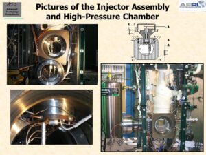 irmation through the examined atomization criteria, and the visual lack of any drop; the relevancy of current injection models and some drop vaporization/combustion results under conditions where gas-jet like appearance is observed should be reexamined.
In many power production machines liquid fuel is injected into a high temperature and pressure combustion chamber to react with an oxidizer for release of the fuel’s chemical energy. Such relevant examples are rocket, gas turbine, and diesel engines. In the designs of chemical rocket engines liquid fuel and oxidizer are injected through openings to form round jets, coaxial or impinging types, entering into the hot and elevated pressure environment of the combustion chamber.
Simple thermodynamic analysis of the rocket thrust chamber (combustion chamber plus the expansion nozzle) shows that, for a given thrust, the rocket size may be decreased as chamber pressure is increased. The extent of this benefit, however, is lowered by other considerations such as higher thrust chamber stresses, heat transfer rates, and pump power and size. As far as the combustion is concerned, effects of increased chamber pressure are to decrease dissociation of the molecules and hence increase the effective heat release. Higher effective heat release, theoretically, delivers higher specific impulse. Hence motivation towards higher chamber pressures are justified. In diesel engines, the higher the compression ratio the higher the thermal efficiency, being the desired trend. In addition, extremely high in-cylinder liquid fuel injection pressures of up to 200 MPa are employed for better air/fuel mixing to reduce soot formation and EPA-regulated exhaust smoke. In gas turbine engines, high compressor pressure ratios (translate into high chamber pressures) and elevate!1 combustor exit temperatures lead to better thermal efficiencies.
In all of the above examples, due to the high pressure trends and existence\ of high temperature in the combustor, injected liquid may find itself near or even above the thermodynamic critical condition. For example, the Space Shuttle main engine thrust chamber pressure is about 22.3 MPa. And, the combustion chamber pressure for Vulcain (Ariane 5) with liquid H2/liquid O2 can reach up to 10 MPa while a record pressure of nearly 28.2 MPa has been reported. Very little information is available on liquid jets injected into supercritical condition. And this leads to our motivation in initiating an organized and systematic experimental effort investigating liquid jets under sub- and supercritical conditions.


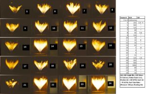
- Anatomy of an Isothermal and Burning Hollow-Cone Spray Relevant to Gas Turbine Combustion:


Spray combustion is of central importance from practical, theoretical, and computational points of view. The ultimate objective is the complete understanding of important processes in spray combustion to assist in designing a more fuel efficient and less environmentally destructive power generation/conversion devices. Gas turbine engines, liquid rockets, furnaces, incinerators, and diesel engines are typical examples in which spray combustion is of prime interest. There are several questions that investigators have tried to answer through experimental efforts. Among them are: 1. Do droplets burn individually or as a group? 2. How is flame stabilized? 3. What are the effects of air swirl and combustion on spray structure? 4. What is the nature of interaction between gas and drop flow fields? Answers to these and other pertinent questions are important to our understanding of spray combustion. Ultimately they provide information for intelligent and efficient designs of combustors in which fuel sprays are used.
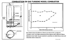
Although considerable progress has been made towards a better understanding of spray combustion, we are still far from a coherent and complete understanding of this subject. The flow field in a gas turbine combustion chamber is three-dimensional and complex with interaction between primary jet, dilution jet, swirler air, wall cooling air, and fuel flows. Therefore, to have detailed experimental measurements, a swirl-stabilized combustor was constructed to simulate a part of the events occurring in an actual liquid-fuel-fired combustion chamber. The objective o f this paper is to report experimental results taken from a spray with and without combustion within a single combustor and with identical boundary and initial conditions. We would like to investigate effects of combustion alone on the droplet flow field and spray characteristics in a swirl-stabilized flame combustor. Also, these results may be used for modeling and computational efforts.
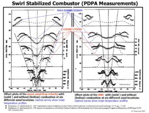
Limits at which a flame is either extinguished or blown off in a model swirl-stabilized combustor were determined. At each fixed dilution air flow rate, increasing the swirl flow rate eventually extinguished the flame. Decreasing it caused the flame to lift up and be blown out of the combustor. Effects of combustion on the spray were to increase the mean drop velocity, decrease the rms of drop velocity fluctuations, and to raise the SMD values. The spray was also widened by combustion. Radial profiles of average uncorrected temperature were also measured, indicating a peak and a minimum due to the reversed flow observed around the center line of the spray. From the long-time exposure flame pictures, mean axial drop velocity, and temperature profiles three radial zones were defined; a preheat/reacting zone, a turbulent flame-brush zone, and a burned gas zone. Fuel volume flux profiles indicated negligible drop vaporization and/or burning up to a distance of 25 mm from the nozzle. Velocity number distributions at different radial points for the no-combustion case at an axial distance of 55 mm from the atomizer were symmetric in shape only close to the peak of the mean drop velocity profile. Corresponding distributions with combustion were fairly symmetric and quite different in behavior than the non-burning case at all "comparable" radial positions. Shapes of the drop size number distributions at "comparable" points were also different for the two cases studied. Size-classified axial drop velocities showed strong size-axial velocity correlation near the atomizer which diminished away from it. Axial gas velocity results by LDV not only confirmed the existence of a central vortex core region but showed larger recirculation zone than one may judge by mean drop axial velocity profiles.
To investigate the characteristics and anatomy of a hollow-cone spray, with and without combustion, somewhat similar to those occurring in the primary zone of gas turbine combustion chambers or within the furnaces and oil burners, a swirl-stabilized combustor and a water-cooled stainless-steel gas sampling probe were designed. A kerosene spray was generated by a simplex atomizer with a nominal included-cone-angle of 30 degrees. Swirling air with a calculated nominal swirl number of 0.36 was produced with a swirl plate having an exit air velocity vector of 30 degrees with respect to the chamber axis. A laser Doppler velocimeter (LDV) was used to measure the axial gas velocities and investigate the flow field in the combustor without fuel injection. A phase Doppler particle analyzer (PDPA) was employed to measure the drop size and mean values of the axial drop velocity with and without combustion. Air and fuel flow rates and other conditions were kept identical for reacting and non-reacting cases to see effects of combustion alone on the spray. Finally, a gas chromatograph (GC) was employed to measure the gaseous species concentrations such as hydrogen, oxygen, nitrogen, carbon monoxide, methane, and carbon dioxide in this combustor.
Click on the link to watch movie of the Swirl Stabilized Combustor test: https://www.dropbox.com/s/fx06cgug96skanw/Swirl%20Stabilized%20Gas%20Turbine%20Combustor%20Chehroudi.mpg?dl=0.


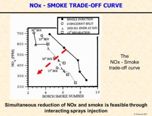
- A Novel Approach for Simultaneous NOx and Smoke Reduction in Diesel Engines: Interacting Sprays Injection System:


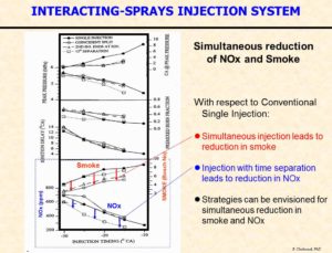
Many in-cylinder injection approaches were proposed for simultaneous reduction of nitric oxides (NOX ) and smoke in diesel engines with various degrees of success in operation. In this paper, some results from a novel and promising technique referred to as Interacting-Sprays injection concept is presented. A single-cylinder compression-ignition two-stroke research engine with optically-accessible head mounted on a high-speed CFR (cooperative fuel research) engine crankcase is used to investigate the combustion and emission characteristics of this injection system. The interacting-sprays injection system produces two separate independently-controlled liquid fuel spray injections with a good degree of adjustability with regard to their fuel quantities and injection timings. The impingement schedule of the two sprays on each other at the right time and place inside the combustion chamber is the key to the success of the interacting-sprays injection system. Results are presented that show the effects of the varied injection system characteristics on the combustion and exhaust emissions ( NOX and smoke). The effects of the injection timing and time separation between the first and second injections of the interacting-sprays injection system are explored. Conditions are identified for which a favorable influence on both smoke and NOX production is observed. A promising and new injection system and strategy are therefore proposed as a result of the data acquired in this study.
Stages of the Project:
-
- Optically-accessible single-cylinder D.I. diesel engine with impinging sprays.
- Nature of interactions between sprays using Mie scattering.
Pusbka, D., Sinko, K., and Chehroudi, B., Society of Automotive Engineers, Paper 940679. 1994.
Sinko, K., Pushka, D., and Chehroudi. B., Journal of Flow Visualization and Image Processing, Vol. 2, pp. 93-1 12. 1995.
-
- Vapor and liquid phase interactions by laser induced fluorescence (exciplex).
Campbell, P.H., Sinko, K. M., and Chehroudi B. The Combustion Institute. Central States Meeting. University of Wisconsin, Madison, Wisconsin, pp. 15-20, 1994.
Campbell, P. H., Sinko, K. M., and Chehroudi, B. Society of Automotive Engineers, Paper 950445. 1995.
Chehroudi, B., Sinko, K., M., and Campbell, P. H. Journal of Flow Visualization and Image Processing, 1996.
-
- Measure NOx and smoke in the exhaust: Potential for simultaneous reduction.
Sinko, K. M.. Shih, S., and Chehroudi, B. Society of Automotive Engineers, 1996 Congress and Exposition, Paper 960839, February 26-29, 1996.
Chehroudi, B., Sinko, K. M., and Shih, S. Society of Automotive Engineers. 1996 Future Transportation Technology Conference, Paper 961678, August 5-8, 1996.
Key Findings of Research:
-
- The key concept in the proposed Interacting-Sprays injection system is the interaction of the two jets (or sprays) at the right time and place inside the combustion chamber to achieve reduction in smoke and NOX emissions. Although not fully tested, the location of the jets impingement and the impingement angle are expected to be two important parameters for optimization.
- The key concept in the proposed Interacting-Sprays injection system is the interaction of the two jets (or sprays) at the right time and place inside the combustion chamber to achieve reduction in smoke and NOX emissions. Although not fully tested, the location of the jets impingement and the impingement angle are expected to be two important parameters for optimization.
-
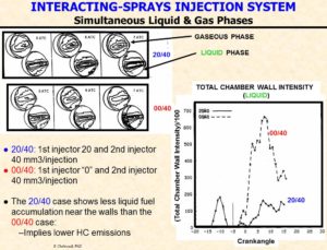
- It appears that the interaction between the two sprays within the combustion chamber can cause a reduction of the near-wall liquid fuel accumulation, which should reduce unburned hydrocarbon emission. Also, from flow visualization works by the authors, it was suggested that spray/spray impingement has enlarged the regions where liquid fuel sprays present and consequently increased the potential for enhancement of air utilization within the combustion chamber.
-
- Results indicate that stronger interactions between the two injection pulses (i.e. spray/spray impingement) early within the ignition delay period is critical to a reduction in soot formation. Simultaneous double injection with strong spray/spray impingement produced the lowest soot in our research engine (reduction by about 45 %). This is explained to be due to additional mixing and atomization effects of the impingement which reduced and disrupted soot-producing rich zones within the core of the sprays.
-
- For effective NOx reduction the second injection pulse should start near or a little beyond the ignition delay period in order to lower the local burned and burning gases temperatures hence reducing the NOx formation rate (reduction by 20 to 35 %).
-
- One strategy using the proposed interacting-sprays injection system to simultaneously reduce NOx and soot would be double near-simultaneous injection (for soot reduction) retarded for NOx reduction.
-
- Based on the results presented here a new low-pressure interacting-sprays double-injector injection system is proposed in which the two injectors are strategically located to cause early spray/spray impingement (for example by near-simultaneous injections) for soot reduction, while one of the injectors produces a late second spray to lower the NOx formation rates. Note that a new centrally-located single-injector injection system can possibly be designed to achieve the spray/spray impingement concept and strategy introduced in this paper. Obviously, the actual final design for use in production engines may not be identical to what is used for research purposes, but should incorporate the ideas and the concepts that are introduced in this paper. Due to the added atomization and rich spray-core disruption effects of jet/jet impingement this proposed injection concept may not require a very high injection pressures used to enhance mixing in order to lower exhaust smoke number. This, additionally, can lead to lower weight of the injection system.
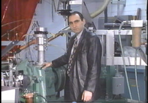
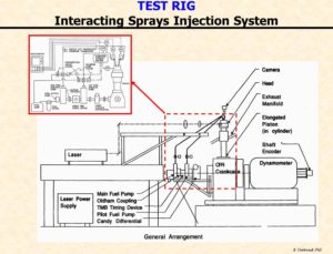
The video clip to the right (click on the image to run the video) describes the engine experimental setup for the so-called "Interacting Sprays Injection System" sponsored by the General Motors. The work is to explore the potential for simultaneous reduction of NOx and Soot in diesel engines through an innovative interacting/ impinging sprays concept. This design, first proposed by Dr Chehroudi for diesel engines, was inspired by his work on impinging jets in liquid rocket engines such as Apollo Project. For more on impinging jets in rockets see "Comprehensive Review of Liquid Propellant Combustion Instabilities in F-1 Engines" or "Recent Experimental Efforts on High-Pressure Supercritical Injection for Liquid Rockets and Their Implications."

Also, see Dr Chehroudi's presentation on Interacting-Sprays Injection System by clicking on the following Link: Interacting Sprays Injection System

Also, see Dr Chehroudi'd presentation to Bosch Corporation in Europe: Bosch-Univ Salento - ATC:
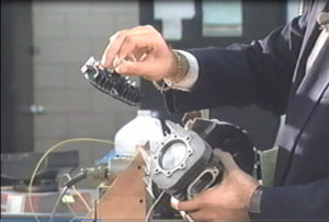
The video to the right (click on the image below to run the video) describes details of the components used and their interconnections for the Interacting-Sprays Injection systems. (described by Dr. Ken Sinko).

- Simultaneous visualization of the liquid and vapor phases of sprays by laser-induced fluorescence (Exciplex Technique):

An optically accessible single-cylinder compression-ignition two-stroke research engine equipped with dual-injection system, image acquisition, and control system have been designed to acquire two-dimensional images of the pilot (or first) and main (or second) diesel fuel sprays. The engine construction permits illumination of the sprays by a thin sheet of laser light from a pulsed Nd:YAG laser frequency tripled to operate at the ultraviolet wavelength of 355 nm. The liquid fuel was decane with TMPD-naphthalene dopant dispersed in it. After ultraviolet excitation by the pulsed laser, liquid fuel regions fluoresced with a spectrum centered at the wavelength of 380 nm, while vapor regions fluoresced with a spectrum centered at 470 nm. This approach, called Exciplex technique, was applied to permit simultaneous acquisition of the liquid and vapor fuel regions in the cup-in-head geometry of the combustion chamber. The results from limited conditions suggest that existence of the pilot injection affects the chamber flow field, particularly in the near-wall region, in such a way that less liquid fuel accumulation occurs with pilot (or first of the two) injection scheme thus should reduce hydrocarbon emission. The area spreading rate of both vapor and liquid phases within the visualization plane were linear in early stages with former having a higher rate. Close to the two-spray-impingement time, vapor phase area penetration is reduced to near zero, while liquid continues linearly but at slower rate than its initial value. Both air utilization and evaporization are therefore reduced. Also, based on this and work by others, the suggestion is made that to achieve optimum simultaneous reduction in soot and NOx, the timing between the pilot (or first) and main (or second) injections (dwell) should be chosen with due consideration of the interaction between the swirl flow and pilot (or first) spray and the relative magnitudes of the ignition delay period with respect to the dwell.
In recent years a great deal of attention has been given to the fluid mechanics of in-cylinder processes and fuel injection systems in DI diesel engines to increase fuel economy while decreasing exhaust pollutions. As federal EPA emissions standards on exhaust pollutants from diesel engines become more stringent, complete understanding of the vaporization and mixing processes of injected fuel becomes more important. It would be significantly beneficial to reduce exhaust emissions by means of injection parameters and thus avoid costly exhaust aftertreatment.
Deeper understanding of the manner in which liquid and vapor phases of the pilot interact with the ones of the main spray may bring more clues to a better implementation of the pilot, split or interacting-sprays injection strategies. In addition, this information is expected to be of use for interpretation when engine-out emissions are measured. This research concentrates on the presentation and the analysis of results obtained in an optically accessible single-cylinder compression ignition research engine equipped with a dual-injector pilot or interacting-sprays injection system. Exciplex technique is used to acquire simultaneous images of the vapor and liquid phases of both pilot (or first) and main (or second) sprays. Here, the term “pilot injection” is used in the same general sense and meaning as the split injection. Also, the nozzle pressure is much less than the high-pressure injection work of Shundoh et al. However, in our case, the injected pilot (from the first injector) should burn near the nozzle and the main spray (from the second injector) would be able to entrain the burned/partially-burned gases and thus the pilot injection effects may be stronger than the high-injection-pressure conventional system when pilot injection is used.
One effective measure to reduce NOx emission is to retard the injection timing. This allows combustion to shift more into the expansion strike and consequently decrease the bulk gas temperature. However, this deteriorates the efficiency and increases the bsfc. Therefore, there are limits in retarding the injection timing.
The technique employed to visualize liquid and vapor phase distribution is the laser-induced fluorescence known as “exciplex.” This approach was originated by Melton and has been employed for investigation of evaporating fuel sprays by several investigators, including Bardsly et al., Diwakar et al, and Bower and Foster. In this technique, a base fuel is doped with a small quantity of organic dopants. After excitation with an intense UV light, the dopants fluoresce at different colors (i.e., wavelengths), depending on whether they exit in the liquid or vapor phases.


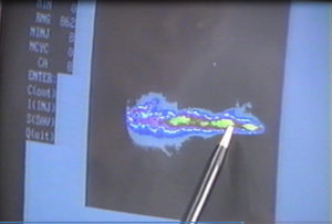
This video (click on the right image to run the video) describes some of the results acquired from a single-cylinder visualization engine showing laser induced visualization of the spray injected into the combustion chamber.


An oscillating piezoelectric beam was used on the prefilming surface in a two-dimensional model of the prefilming-type aircraft fuel atomizer to interact with the periodic phenomena occurring inside the nozzle and just at the atomizing exit-edge of the prefilming surface. The oscillating beam was designed such that its second mode of oscillation resonated at frequencies close to the above-mentioned periodic phenomena. It was shown that the spray Sauter Mean Diameter (SMD) and mean drop velocity profiles became more uniform at a distance of 50 mm from the nozzle for the condition tested. Cross-sectional-averaged SMD decreased slightly as a result of this novel feature.
In gas-turbine aircraft engines, fuel nozzles are used to atomize liquid fuel for use inside the combustion chamber. Performance and design of these fuel nozzles are among the key elements for efficient and clean combustion of fuel in aircraft engines.
The liquid breakup processes for the three commonly-used fuel nozzles producing hollow-cone sprays namely, pressure-swirl, air-assist, and airblast types are briefly as follows: In a pressure-swirl nozzle the breakup of a high-velocity conically-shaped liquid sheet occurs outside the nozzle under two disintegration modes called wave amplification and perforated sheet, see Dombrowski and Fraser (1958), Fraser et al. (1962). Although at least two disintegration modes were identified, only one mechanism of drop formation has been accepted. The disintegration of a sheet yields ligaments that then break up into rows of drops according to the classical description of Lord Rayleigh (1879).
In air-assisted types, particularly at low liquid flow rates, the atomization is improved by impingement of a high-velocity gas stream on a relatively low-velocity liquid stream, either internally or externally. See, for example, Gretzinger and Marshall (1961), Mullinger and Chigier (1974), and Mao et al. (1985). In one widely-used design of airblast atomizer, called "pre-filming," liquid (fuel) is first spread out in a thin continuous sheet and exposed to a high-velocity air on one side which is then blasted by another air jet just at the exit plane of the nozzle, see for example Lefebvre (1983) and Aigner and Wittig (1988).
Review of the past work on hollow-cone sprays from gas turbine nozzles clearly indicates considerable progress in our basic understanding of spray formation mechanisms and the existence of a large body of drop size measurements data for different operating and design parameters. However, for a given nozzle, and at a fixed operating conditions (to have constant air-fuel ratio), no provision for changes in drop size distribution exists. Existence of such an extra parameter would be very beneficial as the drop size distribution can be tailored to provide better performance of and/or lower emission from the combustion chamber. For example, excessively long burning or evaporating times for the large drops injected into the liquid fuel spray flame will lead to incomplete combustion and thus increased emissions of HC and CO. Also NO„ emissions are lowered by a reduction in mean drop diameter, see Rink and Lefebvre (1989). Since drop collision and coalescence are not important in hollow-cone sprays (the type used in gas turbine aircraft engines) one would expect effective size modulation by methods that interfere with the spray formation and breakup processes inside or very close to the nozzle. Therefore, the objective of this work is to assess the degree of effectiveness of a proposed method to interact with the atomization and liquid breakup processes in order to convert commonly-used prefilming fuel nozzles in gas turbine applications into adjustable (even if with limited range) size-distribution atomizers while working at a fixed operating condition.
Review of works on the effects of the fuel nozzle geometrical dimensions on its performance by Taylor (1950), Binnie and Harris (1950), Dombrowski and Munday (1968), Lefebvre (1983), Rizk and Lefebvre (1985), Shaw and Jasuja (1985), Sattelmayer and Wittig (1986), and others show that the drop size distribution, or a characteristic average drop size based on this distribution, changes when geometrical dimensions are varied. In principle, one can use this fact and design a variable geometry nozzle to produce variable spray drop size distribution. However, the required mechanical movements and the additional weight make this approach less desirable.
Acoustic waves and mechanical vibrations have been used to generate mono-size (and adjustable) droplet generators. In one widely used design by Burglund and Liu (1973) a vibrating orifice is used for monosize droplet generation. Application of acoustic waves (in the liquid) has also been considered in the design of ink jet systems. Ink drops from an ink-jet printer are ejected by an array of "print-heads" which is basically a cylindrical cavity filled with ink with one side connected to an orifice and the other to a steel plate on which a piezoelectric crystal is bonded. Oscillation of the crystal causes droplets of certain (controlled) size to be ejected, Elger and Adams (1987). This same design was also employed to generate size-controlled droplets, see Ashgriz and Yao (1987) and Orme and Muntz (1987). In yet another technique, drops were formed by the vertical mechanical vibration of a liquid column. Drops were ejected from the free surface of the liquid.
It was shown by Hashimoto and Sudo (1987) that drop sizes from this interface could be changed by the vibration frequency. Ultrasonic atomizers are based on the principle that liquid droplets are produced when powerful high-frequency (10 to 2000 KHz) sound waves are focused onto the liquid surface, see Gershenzon and Eknadiosyants (1964).
Most of the aforementioned approaches are used as droplet generators and they generate low-velocity droplets with low liquid fuel flow rates which are not useful for aircraft gas turbine engine applications. Also, to minimize soot formation in the primary zone of the combustion chamber, it is desirable to premix the fuel and air prior to combustion, hence the use of airblast fuel nozzles in aircraft gas turbine engines. However, all of the above experiments suggest the possibility of mechanical and acoustic excitations for drop size manipulation in gas turbine fuel nozzles. The proposed design, with further justification for its potential in drop size manipulation, are discussed in the next section.


- This video (click on the right image to run the video) shows some more details of the test engine setup and actual operation of the engine in order to acquire data from fuel sprays interacting inside of the engine. Towards the end of the video one can hear the sound of fuel/air autoignition in this diesel engine under the skip-fire operating mode.
- Heat Release Analysis in a Singe-Cylinder Two-Stroke Production Engine:
The net heat release rate and net heat release fraction for a spark-ignited (SI) single-cylinder two-stroke, production engine were analyzed using the one-zone model. Three different throttle positions and four engine speeds for each position were considered for this study. The method used required cylinder pressure and crank-angle data which were obtained from a pressure transducer mounted in the cylinder head and a shaft encoder connected to the crankshaft. An effective routine referred to as the overlap method was used to smooth undesirable oscillations on the heat release rate curves after investigation of several different approaches.
Parameters such as maximum heat release rate, rapid burn angle, combustion duration, maximum heat release rate angle, imep, bmep, etc. were calculated and discussed. It is shown that the trends for the results obtained by this simple model can be adequately explained using independent information regarding the effects of parameters such as residual burned mass fraction, equivalence ratio, and turbulence on flame burning speed. For not-too-rich mixture, a parameter is proposed to provide information regarding the short-circuiting in two-stroke engine. On this basis, "simple" one-zone heat release calculations can be used for rapid computations of important combustion-related parameters for engine analysis and diagnostics in two-stroke engines.
This video clip (click on the right image to run the video) shows a test setup of a single-cylinder small two -stroke gasoline-fueled engine on a small dynamometer. The engine head is equipped with a pressure transducer to provide traces for combustion signature diagnostics. In this case, a one-zone model is used to calculate the heat release rate and mass fraction burned information to understand the combustion characteristics of this engine.


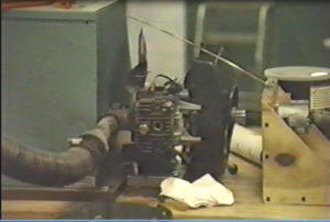
This video clip (click on the right image to run the video) describes a small engine test setup showing a dynamometer along with necessary piping system for the intake and exhaust as well as measurement systems needed for air and fuel flows rates into the engine/
Results have been published in the literature. For example, see Rohrer, R. and Chehroudi B., 1993. Preliminary Heat Release Analysis in a Single-Cylinder Two-Stroke Production Engine, Society of Automotive Engineers, 1993 Congress and Exposition, SAE Transaction Paper 930431, March 1-5. Here is a video to download the video file:Small two stroke engine tests Chehroudi.
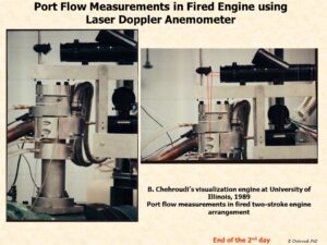
- Intake-Port Flow Behavior in a Motored and Fired Two-Stroke Engine:
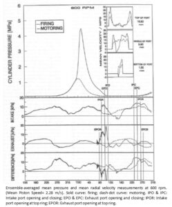
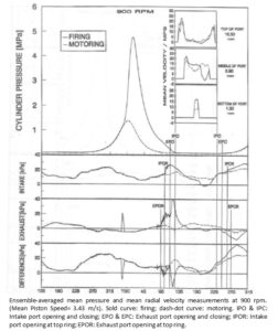
Velocity information was collected from an intake port of a single-cylinder piston-ported two-stroke engine by a laser-Doppler velocimetric (LDV) system to better understand and quantify the behavior of intake flow exiting into the cylinder during the scavenging process. Ten measurement locations were chosen along a vertical line through the center of the port exit area. Motored, fired (skipfired), and steady (stationary engine) radial velocity measurements were recorded at engine speeds of 600, 900, and 1200 rpm along with cylinder, intake (two positions), and exhaust pressure data. The ensemble-averaged mean radial velocities during motoring, when plotted versus crank angle, are generally flat over most of the port area and influenced by changes in pressure differential between the intake and exhaust ports. During the initial phase of the port opening, a high-velocity jet exits from the port, causing a peak in the mean radial velocity profile.
As the port opening area increases, the reattachment point within the port passage apparently moves toward and beyond the exit plane of the port, resulting in near-zero velocities for the measurement points close to the top of the port. Mean velocities measured after the firing cycles are strongly affected by the expansion waves in the intake system, which induce backflow of cylinder gases at 600 and 900 rpm. At 1200 rpm, velocities for the motoring and firing cycles are very similar since the pressure differential between the intake and exhaust ports during the intake period are similar for the two cases. The root mean square (rms) velocity fluctuations are generally higher in the fired engine over all the measured engine speeds. Properly normalized ensemble-averaged mean velocity profiles along the measured direction are not shaped like a top hat but are very similar for motored, fired, and steady engine conditions, particularly at higher engine speeds. The volumetric flow rate is estimated using LDV results, compared with the actual measured value, and discussed.
Two-stroke internal combustion engine has attracted a great deal of interest in some applications as a possible replacement for or alternative to the four-stroke design because of its high power-to-weight ratio, mechanical simplicity, and compact size. These attributes are particularly interesting to automobile manufacturers with respect to reducing the overall engine weight and power plant size, allowing a lower hoodline for better aerodynamics as well as more space for passengers and cargo.

Early two-stroke engines were known for their characteristic exhaust plume containing high levels of unburned hydrocarbons (UHC) due to partially reacted and unreacted engine fuel and lubricant brought about mostly by fuel flow-through or "short-circuiting" fuel losses. Today, with the advancement in electronic engine management systems and fuel injection schemes, direct injection of the proper amount of fuel into the cylinder after port (intake and exhaust) closure can help eliminate much of the UHC present in the exhaust. With the addition of catalytic aftertreatment of the exhaust gases, development continues on two-stroke engines to meet the current and future emission standards, allowing them to compete with four-stroke engines as a viable alternative in a variety of applications.
To maximize performance and improve the operational stability of two-stroke engines, an understanding of the complex scavenging process has become increasingly important. The scavenging process has been difficult to understand because it is influenced by so many factors, among them the designs of the intake and exhaust ports, scavenging type, combustion chamber shape, and intake and exhaust system designs. The main purpose of ideal scavenging is to fill the cylinder with fresh charge and purge the burned gases left from the previous cycle by perfect displacement with no mixing between the fresh charge and burned gases. Additional concerns are to prevent short-circuiting fuel losses and the formation of dead zones or pockets where burned gases can become trapped [1]. Intake port design affects the scavenging process as small changes in individual port design and placement can alter the scavenging behavior and overall efficiency of the engine [2]. The flow pattern established by the intake ports during the engine scavenging process is important to displace in-cylinder burned gases left from the previous cycle out to the exhaust and ensure a fireable charge near the sparkplug at the time of ignition to guarantee stable combustion and smooth engine operation.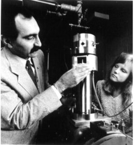
Understanding of the fluid dynamical processes involved during the scavenging period, especially the behavior of the intake port flow, is an important step in gaining a more complete understanding of the scavenging process. This should ultimately lead to a more energy-efficient and environmentally favorable two-stroke engine design.

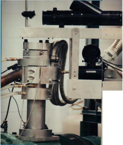
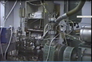
The images to the right show an optically accessible engine for combustion and flow studies using laser diagnostics such as Laser Doppler Velocimeter (LDV), Phase Doppler Particle Analyzer (PDPA, Exciplex method, high-speed visualization of in-cylinder phenomena, and spectroscopy. The engine head can be readily changed for either compression ignition (diesel) or spark ignition (SI) engine studies.
Results have been published in the literature. For example, see Schuh, D. and Chehroudi, B., 1992. LDV Measurements of Intake Port Flow in Two-Stroke Engine with and without Combustion, Society of Automotive Engineers, 1992 Congress and Exposition, SAE Transaction Paper 920424, February 24-28.
- Measurements of the Three Components of the Velocity in the Intake Ports of an I. C. Engine using Laser Doppler Velocimetr (LDV):
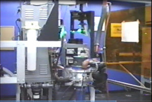
This video clip (click on the right image to run the video) is about a single-cylinder optically-accessible research engine setup for measurements of intake flow dynamics using Laser Doppler Velocimeter (LDV). A unique rotating mechanism was designed for convenient and rapid measurements of the velocity vectors at sufficiently large number of points at the plane through which flow just enters the cylinder.
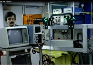
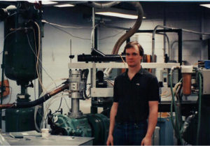
This video clip (click on the right image to run the video) shows operation of an engine for intake port flow measurements using Laser Doppler Velocimeter (LDV). The entire transmitting optics are on a lathe machine base to enable precise XYZ traverse for easy optical alignment/measurement purposes as well as achieving convenient rotation of portion of the transmitting optics along the engine axis for rapid intake port flow measurements (engine was under two-stroke operation). The person in the image is Konstantinos Boulouchos who was a visiting researcher to the laboratory (currently a professor at the ETH Zurich, Switzerland).
Results have been published in the literature. For example, see Bardsley, M. E. A., Boulouchos, K., Gajdeczko, B., Chehroudi, B., and Bracco, F. V., 1989. Measurements of the Three Components of the Velocity in the Intake Ports of an I. C. Engine, Society of Automotive Engineers, 1989 Congress and Exposition, SAE Transaction Paper 890742, February 27 - March 3.
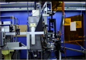
This video clip (click on the right image to run the video) shows more details of the test setup for laser diagnostics in single-cylinder optically-accessible research engine.
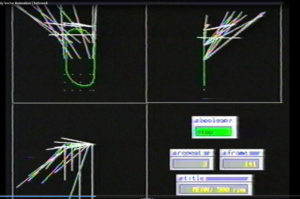
This video (click on the right image to run the video) shows vector plots of the velocity field for an inlet port at the plane where the flow just enters the cylinder. The movies show three perpendicular views for the velocity vectors at the aforementioned measurement plane. For 3D visualization of velocity vectors click here: 3D_Vel_Vector_Animation.
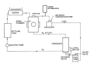
- The image to the right shows an schematic diagram of the high-pressure high-temperature closed-loop spray chamber for liquid atomization and spray characterization studies.
This video (click on the right image to run the video) shows details of the high-pressure and high-temperature spray chamber for liquid atomization and fuel injection studies. The chamber has four large-sized quartz windows providing access at intervals of 90 degree angle. The chamber can be operated under steady-state condition for several hours.
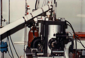
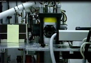
- The images to the right show a high-pressure and high-temperature spray chamber with optical access through four large quartz widows.
The system is operated under closed loop arrangement and one can perform tests on steady-state or transient sprays continuously and for several hours.
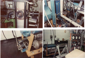
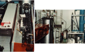
- The images show views of the high-pressure and high-temperature spray chamber.
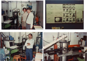
The gentlemen in the upper left corners are Phil Felton and Will Bachalo (Dr Bachalo is the inventor of the Phase Doppler Particle Analyzer (PDPA)). The setup was to test the first prototype of the PDPA under the high pressure and temperature using a dense diesel-type spray from a single-hole nozzle at high injection pressures. More images of the sprays chamber are given below.

Bruce Chehroudi, Jim Semler, Phil Felton, Axel O. Zur Loye, Dom Santavicco, Matt Hall are in the picture at the Prof. Fred Bracco's Princeton University Engine Research Laboratory .
- Images of the high-pressure and temperature spray chamber for liquid atomization and fuel injection research and development are presented here.
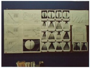
- Sample images acquired from a diesel-type spray (upper row) and conically-opening poppet injector designed for Direct Injection Stratified Combustion (DISC engine program) combustion studies are shown.
The DISC program was a collaboration by General Motors Research Laboratory, Princeton University Engine Research Laboratory, Los Alamos National Laboratory, and Sandia Combustion Research Facility sponsored the US Department of Energy (DOE).
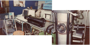
- High-pressure and temperature spray chamber for liquid atomization and fuel injection research and development are shown.
The pictures show a setup for laser optical diagnostics to map spray droplet size and velocity fields. In the movie clip, a setup for transient spray characterization of a gasoline direct injection system by Ford DFI-3 using a diffraction-based drop size distribution (by Malvern) can be seen.
Results are published in the literature. For example, see Laforgia, D, Chehroudi B. and Bracco, F. V., 1989. Structure of Sprays from Fuel Injections - Part II, The Ford DFI-3 Fuel Injector, Society of Automotive Engineers, 1988 Congress and Exposition, SAE Transaction Paper 890313, February 27- March 3.
- On the Intact Core of Single-Hole Full-Cone Sprays (Winner of the prestigious Arch. T. Colwell Merit Award, Society of Automotive Engineers (SAE) )


A voltage was applied between the nozzle unit and fine needles, rods, and screens inserted at various axial and radial positions into atomizing full-cone water sprays and the corresponding electrical resistance was measured in an attempt to determine the shape and length of the intact liquid core. The parameters of the experiment were: room temperature; air compressed at 0.1, 1.0, and 2.9 MPa; injection DeltaP = 13.7 MPa; and five straight-hole nozzles with diameters of 127, 178, 305, 343, and 508 microns, and the same length-to-diameter ratio of 4. The results show that current is carried not only by intact liquid cores but also by atomized unconnected sprays and even across such sprays. Thus the shape of the intact core could be deduced only in the vicinity of the nozzle exit. In the atomization regime, the length of the intact core is found to be proportional to the nozzle diameter and to increase as the square root of the liquid-to-gas density ratio, i.e. x1 = C.d(ρl/ρg)1/2 . where C is approximately equal to 7.
In this research study we are concerned with the structure of Diesel-type sprays from single cylindrical orifices of constant cross section. In particular, we are interested in the configuration of the internal (non visible) part of the spray from the nozzle exit to about 100 nozzle diameters. Many investigators have felt that a conical intact core of liquid should exist in this region but, as far as we know, no direct measurement of this core has ever been made. The existence of this core, and its shape and length, are important both practically and fundamentally. Practically, the shape of the core is a result of the jet breakup process and knowledge of this process is necessary to predict the initial size and velocity of the fuel drops. Moreover the intact core is unmixed fuel that can affect the performance and emissions of Diesel engines. Fundamentally, the breakup of high velocity liquid columns injected into high density gases is the result of an instability that is not fully understood and that has received relatively little attention.


The breakup of liquid jets is achieved through a large variety of atomizers for a large variety of applications. The breakup increases the surface-to-volume ratio of the liquid and, thus, increases the rates of mass, momentum, an d heat transfer, and the vaporization rate. In the case of diesel engines, poppet, pintle, and multihole nozzles are used , the most common being the latter, which usually consists of a group of cylindrical holes from 100 to 300 microns in diameter.
When a liquid is focused through a cylindrical hole into a gas, many modes of breakup are observed. In the one relevant to internal combustion engines, no outer intact length is observed and the jet starts to diverge at nozzle exit. This regime, which has been termed the atomization regime, is reached at high injection velocities, on the order of 100 m/s for the fuel and conditions of engine applications.
Due to their practical importance, many aspects of atomizing jets have been studies extensively. In the 1930s, significant data were gathered on global quantiles, such as downstream drop size distribution, tip penetration rates, and average spray angles. More recent efforts have attempted to determine the structure of atomizing jets. For example, the outer part in the immediate vicinity of the nozzle exit, and the inner part in the same region, have been studies in detail. Recently, laser techniques have been used to measure drop velocity, drop size distribution, and liquid volume concentrations in sprays from air-blast atomizers, but so dilute as to transmit more than 90% of the light.
The application of laser techniques to diesel-type spray is made difficult by the high number density of droplets. Nevertheless, measurements of drop velocity by laser Doppler velocimetry (LDV) in nonevaporating, steady, diesel-type, dense sprays produced by single-hole cylindrical nozzles injecting into compressed nitrogen atmospheres at room temperature have recently been reported by this group. In experiments by Wu et al., measurements were made in regions of the spray where the light transmission was as low as 2%. However, successful simultaneous measurements of drop size distribution have not yet been possible in such sprays due to the high drop number density.
In this paper, we describe an extension of the latter work to vaporizing conditions, where the sprays are injected into compressed nitrogen atmospheres, which were heated to temperatures.

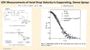
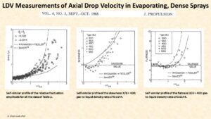
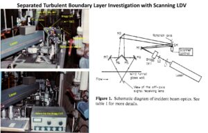
A rapidly scanning one-velocity-component directionally sensitive fringe-type laser-Doppler anemometer which scans the measurement volume perpendicular to the optical axis of the transmitting optics was used to investigate the flow structure of the steady freestream separated turbulent boundary layer of Simpson, Chew & Shivaprasad (1981a). Space–time correlations were obtained for the first time in a separated turbulent boundary layer and showed that the integral length-scale Ly for the large eddies grows in size towards detachment, although the ratio of this length-scale to the boundary-layer thickness remains constant. Results also indicate local dependence of the backflow on the middle and outer regions of the boundary layer at a given instant in time.
The problem of turbulent boundary-layer separation due to an adverse pressure gradient is important for the design of devices such as rocket nozzles, airfoils and helicopter blades, and the design of fluidic logic systems. Using multi-velocity- component directionally sensitive laser-anemometer systems, Simpson, Chew & Shivaprasad (1981 a, b) and Shiloh, Shivaprasad & Simpson (1981) reported extensive experimental results for a nominally two-dimensional separating turbulent boundary layer with an airfoil-type freestream velocity distribution. They concluded that velocity fluctuations in the backflow region are large compared with the mean backflow, instantaneous velocity gradients are substantially different from the mean velocity gradient, and mixing-length and eddy-viscosity calculation models fail in the backflow region. They also suggested that the large-scaled eddies strongly influence the backflow locally.
If large-scaled eddies are largely responsible for the events in the backflow region, then more detailed information such as instantaneous velocity profiles and/or correlation measurements could be used to investigate this matter. A new rapidly scanning laser-Doppler anemometer (SLDA) developed by Chehroudi & Simpson (1984) is capable of measuring mean-velocity profiles, r.m.8. velocity fluctuations and the downstream-upstream intermittency factor ypu at scanning frequencies up to 59 Hz. In addition, measurements of ‘almost ’ instantaneous velocity profiles are also possible if a sufficient data rate is available (Chehroudi 1983).
This work provides new information concerning the flow structures in the separated region using this scanning LDA. Space-time correlation coefficients in the backflow region of a separated flow are reported and analyzed for the first time.


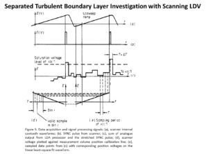
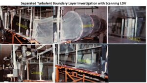


- Heat transfer enhancement through pulsating flow.
![]()
The convection heat transfer coefficient can be increased by inducing pulsating flow through pulse generators, by inducing swirl by inserting a twisted tape into the tube, or by inducing secondary flows by coiling the tube. A tangible example where heat transfer enhancement takes place is blood flow in human vein and arteries. In this research study we used water flow pulsation to investigate the degree of enhancement of heat transfer in pipe flow. In this research project, we imposed an oscillatory flow on the otherwise steady flow in the pipe flow. The flow oscillation was generated through a piston-cylinder reciprocating mechanism. Both the rotation frequency (0.4, 1.25, 4.16, 6.25, 10.28, 12.76 cycles per second) and the amplitude (5, 10, 15, and 25 mm) of the reciprocating piston were varied to investigate their effects on heat transfer coefficient in terms of the Nusselt number (Nu) at different axial positions along the flow direction. The steady flow Reynolds number was at 1,480. In almost all cases, flow oscillation enhanced the heat transfer rates. It was shown that increasing the amplitude of the flow oscillation increased the Nu in nearly all cases tested (except at the downstream end of the test section). Flow oscillation frequency clearly enhances the heat transfer, but at different rates depending on the amplitude of oscillations. The impact of frequency is more observed at low amplitudes of flow oscillations.
| Frequency [Hz] | |||||||
| Amplitude [mm] |
0.40 | 1.25 | 4.16 | 6.25 | 10.28 | 12.76 | |
| 5 | x | x | |||||
| 10 | x | x | |||||
| 15 | x | x | |||||
| 25 | x | x | x | ||||
![]()
![]()
![]()
![]()
![]()
![]()
![]()